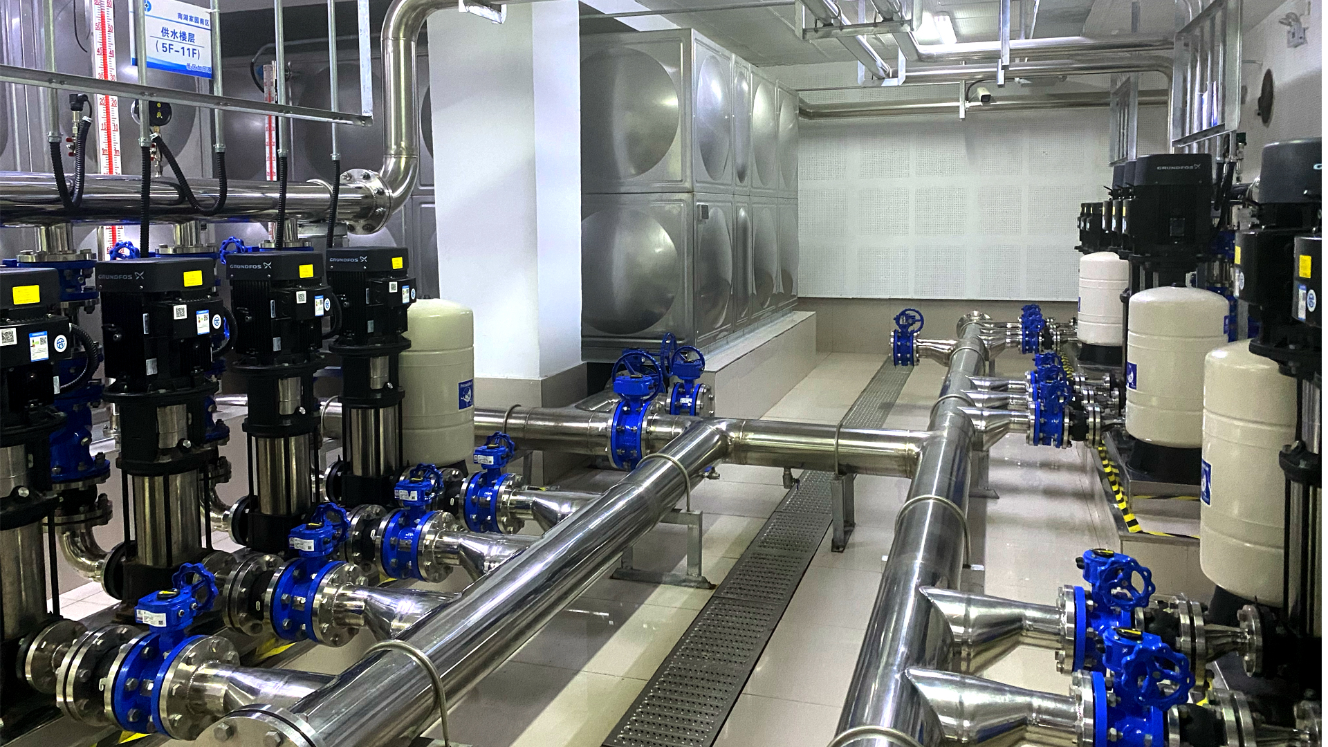
In order to ensure that the water supply equipment in industrial production can automatically adjust the speed and power of the water pump and ensure that the water supply system always maintains a constant water pressure, a variable frequency constant pressure water supply equipment based on PLC is designed. The equipment uses variable frequency technology and constant pressure control strategy to achieve stable water pressure supply. The entire system consists of a water pump, an expansion tank and an intelligent electronic control system. Its outstanding advantages are that it does not require the construction of a water tower, has a small investment, a small footprint, a flexible layout, and uses automatic water and gas regulation; at the same time, it is automatically connected to the tap water network, can still supply water after a power outage, and does not require supervision after debugging.
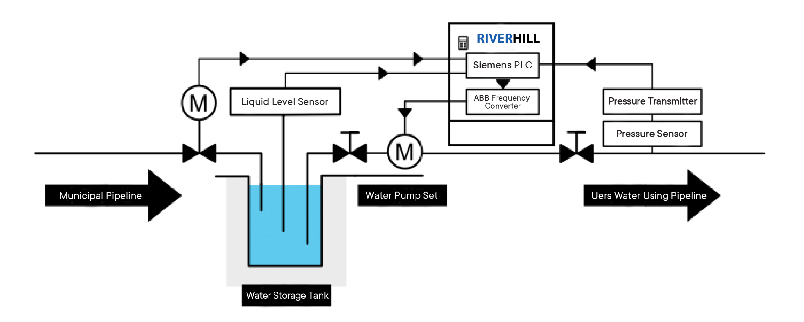
Image: Water Supply Booster System Scheme Diagram
1. Overview
Variable frequency constant pressure water supply equipment is a new type of energy-saving water supply equipment. It uses microcomputer control technology to combine variable frequency speed regulator with motor water pump. Variable frequency constant pressure water supply equipment uses the water pressure at the outlet of the water pump (or the user’s water flow) as the setting parameter, and automatically controls the output frequency of the frequency converter through the microcomputer to adjust the speed of the water pump motor, so as to achieve closed-loop regulation of the user’s pipe network water pressure, so that the water supply system automatically maintains constant pressure at the set pressure value: so that the entire water supply system always maintains the best state of high efficiency and energy saving.
The water supply method of the equipment in this article adopts pneumatic water supply. When the water supply network pressure meets the water use requirements, the system directly supplies water to the water supply network through the bypass check valve; when the water supply network pressure cannot meet the water use requirements, the system pressure signal is fed back to the control cabinet by the pressure sensor, and the water pump operates with variable frequency, and automatically adjusts the speed according to the amount of water used to maintain normal water supply in the system.
2. System Composition and Working Mode
2.1 Equipment Composition
The variable frequency constant pressure water supply equipment consists of an operation display unit, an input module, an output module, a frequency converter, and a power supply unit. Each unit is controlled by a PLC host to achieve constant pressure water supply.
- Input Module: The input module is used to receive signals from external sensors or switches and convert them into digital signals for processing by the PLC host. For example, a pressure sensor can be used as part of an input module to detect the pressure of a water supply pipe.
- Output Module: The output module is used to convert the output signal of the PLC host into a signal that can control an external actuator. For example, the output module can control the frequency converter to adjust the operating frequency of the water pump to achieve a constant water supply pressure.
- Frequency Converter: Frequency converter is an electronic device used to control the speed and output power of the motor. In variable frequency constant pressure water supply equipment, the frequency converter is used to adjust the speed of the water pump to achieve a constant water supply pressure. It receives the output signal of the PLC host and adjusts the operating frequency of the water pump as needed.
- Operation and Display Unit: The operation and display unit is the interface for users to interact with the variable frequency constant pressure water supply equipment control system. It is usually composed of a touch screen or a key panel, which is used to display the system status, receive user input commands, and provide alarm and fault diagnosis information.
- Power Supply Unit: The power supply unit provides stable power supply voltage for the entire control system to ensure normal operation of the system.
The above components are connected by cables or buses to form a complete variable frequency constant pressure water supply equipment control system based on PLC. Through PLC programming and parameter setting, the system can realize functions such as automatic control, monitoring and fault diagnosis, and improve the stability and efficiency of the water supply system. As shown in Figure 1.
Figure 1: System Component Diagram
2.2 Control System Hardware Structure
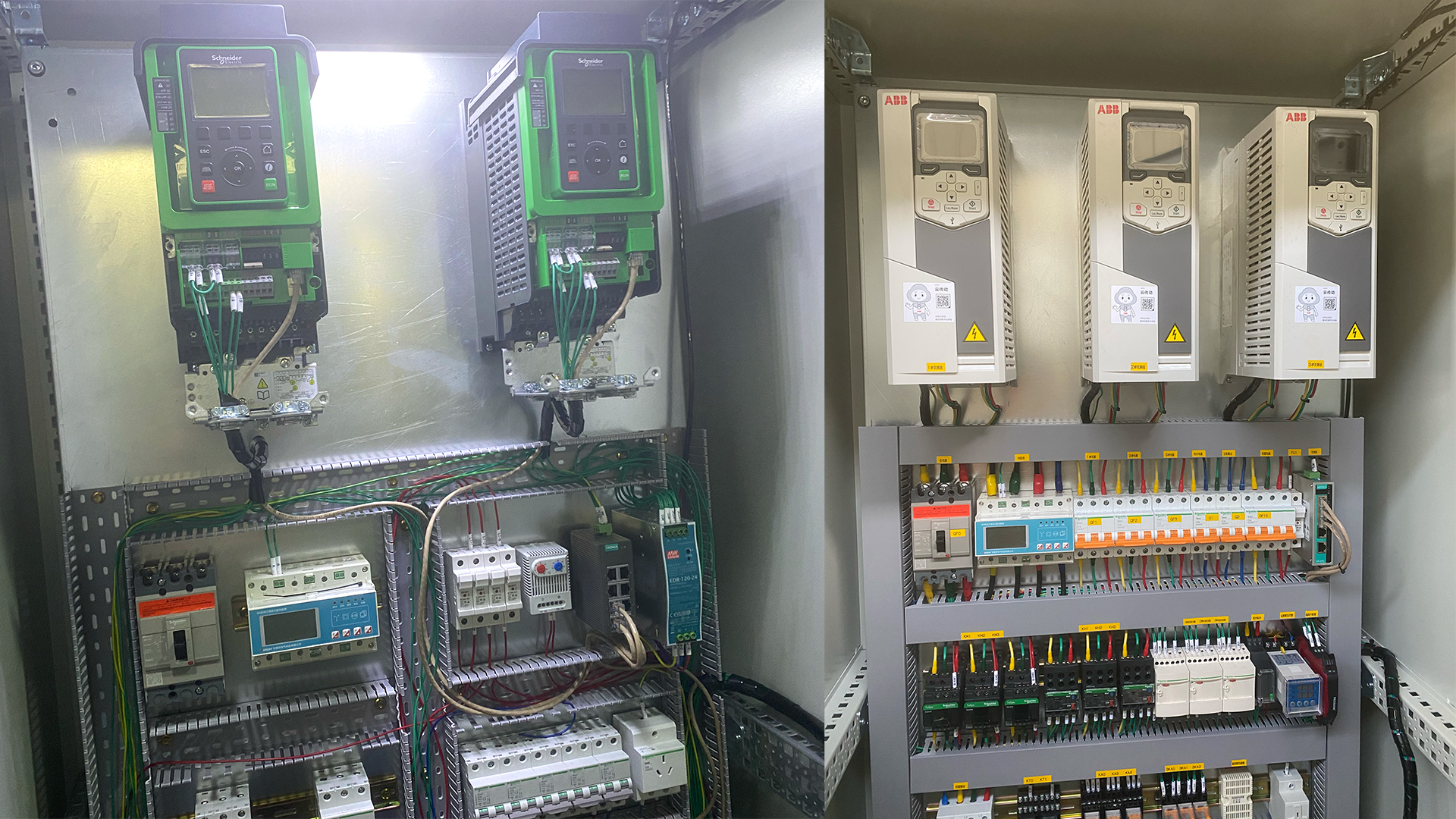
The variable frequency constant pressure water supply equipment adopts an advanced closed-loop control system. The pressure controller on the outlet pipe network samples the water pressure and converts it into a corresponding electrical signal to be transmitted to the intelligent central processor of the frequency converter for control. The frequency converter receives the actual pressure signal of the pipe network and compares it with the pressure value set by the user. The output frequency of the frequency converter is controlled by the deviation value to change the output power of the motor. At the same time, the pump speed is automatically adjusted or the water pump is started and stopped according to the change of water consumption in the pipe network. When the water consumption increases, the output voltage and frequency increase, the pump speed increases, and the water output increases; when the water consumption decreases, the pump speed decreases, the water output is reduced, and the water supply pressure is kept constant. The hardware structure of the control system is shown in Figure 2.
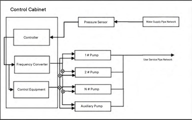
Figure 2: Hardware System Structure Diagram
2.3 Working Mode
During operation, the water pressure sensor and inverter in the constant pressure variable frequency water supply system may fail due to loss and the influence of the external environment. To prevent failure, different modes need to be set according to different needs. The specific available working modes are as follows:
- Constant Pressure Mode: In constant pressure mode, the device will automatically adjust the pump speed according to the set target pressure to maintain a constant water supply pressure. When the water supply pressure is lower than the set target pressure, the device will increase the pump speed; when the water supply pressure is higher than the set target pressure, the device will reduce the pump speed. This mode is suitable for applications that require a stable water supply pressure, such as residential and commercial buildings.
- Constant Flow Mode: In constant flow mode, the device automatically adjusts the speed of the pump to maintain a constant water supply flow. In this mode, the device adjusts the running speed of the pump according to the set target flow to meet specific flow requirements. This mode is suitable for applications that need to maintain a stable flow, such as cooling systems, industrial production, etc.
- Energy Saving Mode: In energy saving mode, the device will adjust the speed of the water pump to provide the best energy efficiency performance according to the actual demand and the pressure change of the water supply pipeline. This mode automatically adjusts the output of the water pump according to the load change to minimize energy consumption and ensure the normal operation of the water supply system. Energy saving mode is usually combined with the function of constant pressure or constant flow mode to achieve a more efficient water supply system.
- Balanced Mode: In balanced mode, the device automatically adjusts the speed of each pump to achieve balanced water supply according to the operating status and needs of multiple water supply pumps. By dynamically balancing the output of different pumps, this mode can improve system reliability, balance loads, and extend the service life of water pumps.
3. System Software
3.1 System Software Flow
The software system consists of a user interface, controller, sensor, variable frequency drive, communication module, and data storage and processing. Its software process includes startup and initialization, user interface interaction, data acquisition and sensor feedback, variable frequency drive control, data recording and alarm, etc.
- Startup and Initialization: When the system starts, each component is initialized. The controller starts and loads default parameters, the communication module establishes a connection with the external system, and the sensor performs self-test and calibration.
- User Interface Interaction: Users interact with the device through the user interface. Users can set target pressure, monitor real-time pressure and flow, view alarm information, etc. The user interface transmits user input to the controller.
- Data Collection and Sensor Feedback: The sensor collects data such as pressure and flow of the water supply pipeline in real time and feeds it back to the controller. The controller receives the data from the sensor to monitor the current water supply status.
- Variable Frequency Drive Control: The controller sends a control signal to the variable frequency drive to adjust the motor speed and output power. The variable frequency drive changes the motor’s operating state according to the control signal to meet the set target pressure.
- Data Recording and Alarm: The system will record key data, such as real-time pressure, flow, pump operation status, etc. If an abnormal situation is detected, such as exceeding the pressure fluctuation range, pump failure, etc., the system will trigger an alarm and display the alarm information on the user interface.
3.2 Parameter Setting
To ensure that the controller executes the control algorithm according to the set target pressure and the data fed back by the sensor, the output of the variable frequency drive is adjusted to achieve constant pressure water supply. The parameters need to be set in advance. The main parameters are:
Set Pressure: Set the required water supply pressure. Set a suitable target pressure value according to the specific application scenario and requirements.
Pressure Selection: Set the allowable pressure fluctuation range. When the actual water supply pressure fluctuates within this range, the variable frequency constant pressure water supply equipment will automatically adjust the working state.
Minimum Starting Pressure: Set the minimum pressure required to start the water pump. When the actual water supply pressure is lower than this value, the equipment will automatically start the water pump to provide the required water pressure.
Pressure Sensor Sensitivity: Adjust the sensitivity of the pressure sensor to ensure the accuracy of the device’s detection of pressure changes.
Feedback Time: Set the device’s detection and response time to pressure changes. A shorter feedback time can adjust the operating state of the water pump more quickly.
The following table is a detailed list of some parameters.
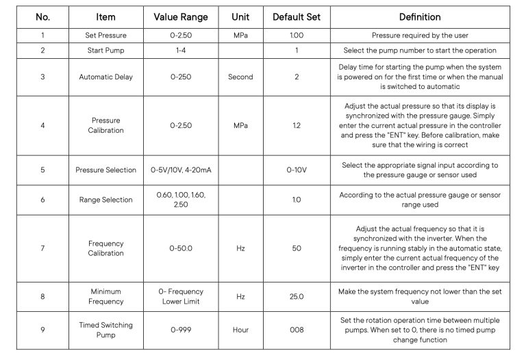
Table 1: Parameter Setting Table
4. System Debugging
After making preparations for the equipment startup, fully open the inlet valve and close the valve on the discharge pipe. Turn on the power, start the program, and enter the system main interface, as shown below.
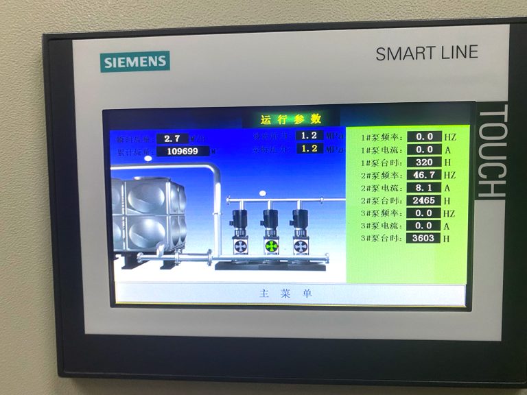
Image 3: System Home Page
5. Conclusion
This paper designs a set of variable frequency constant pressure water supply equipment, which can achieve stable and reliable variable frequency constant pressure water supply, ensure that the pressure of the water supply pipeline fluctuates within the set range, and can respond to user needs and abnormal situations in a timely manner. At the same time, it can adjust and switch working modes according to user settings and real-time feedback.